Refurbishing a Kinesis Classic KB133
I’ve been using a Kinesis Classic keyboard since 2007 when I got one at Google. I did notice some minor issues every few months, but it started to be somewhat annoying only after reading Michael’s list of the issues Kinesis keyboards have. Thanks Michael!
I probably flirted with the idea of replacing the keyboard’s controller following Michael’s instructions for two or three years. But why do it, really.. Things changed last winter when the Esc key stopped working. I switched to a normal totally-boring keyboard I found in the basement. Then I fell in love with the big and accessible Gui key!
Still, to avoid throwing away the old Kinesis I decided to recondition it following Michael’s guide. I ordered three boards because you never know.
Bill of Materials
It’s a shame there is all that space on the Kint board but still we use SMD components which are more fiddly to work with than regular THD components. We’re talking about four resistors and four LEDs, but still, when you have to order them online because that’s exactly what the local electronics shop suggests, it’s quite annoying.
Then there is the ridiculous shipping cost at Mouser and the other online electronics stores. You need to buy 50+ USD of stuff to get free shipping. Ordering from Aliexpress can be very cheap but you have to wait 4+ weeks.
Myself I found the discontinued Teensy 2.0++ at 15 USD including shipping on Aliexpress, and since the other supported Teensy models on the official website were 2-3 times more expensive, I ordered two. One is being used to type this blog post and the other I can’t find anywhere.
The Molex 39-53-2135 connectors were missing altogether in the online shops at the time. I did manage to order Molex 39-53-2134, the 90-degree variant.
Kinesis Classic KB133
The oldest Kinesis model officially supported by Kint is KB500 but it can be used with KB133 just fine. The issue with KB133 is that the semi-rigid FPC extensions of the main left and right groups of keys are supposed to enter in connectors which have to be at a very precise position.
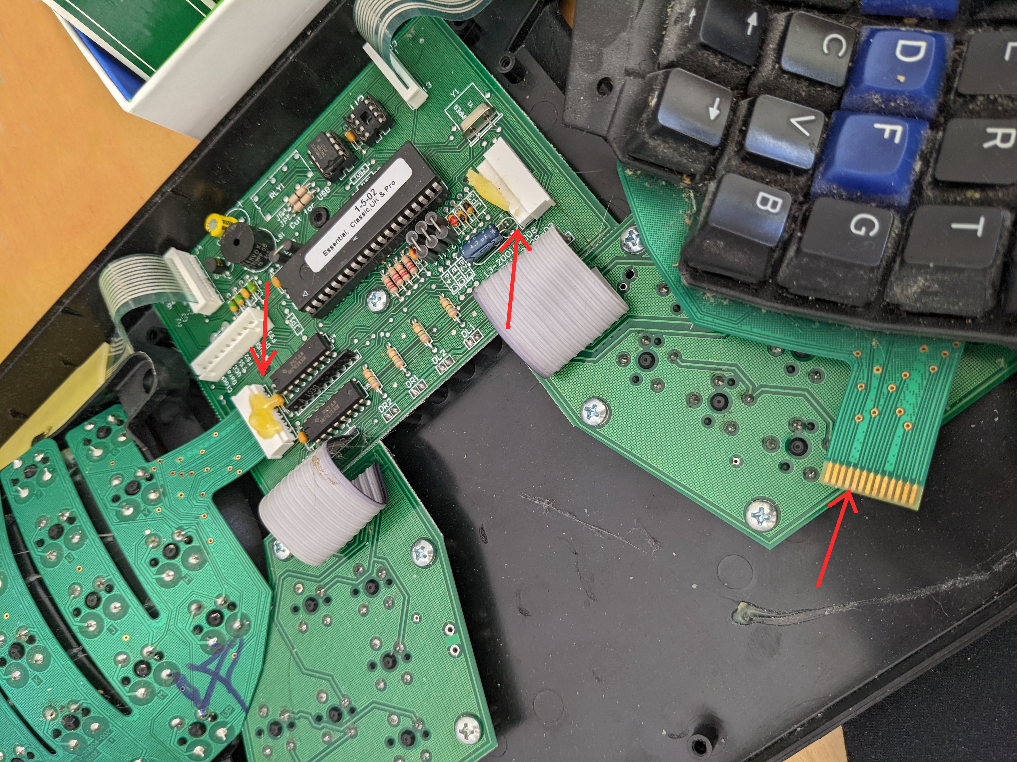
Kinesis KB133 original controller
I had great plans of moving the corresponding Molex connectors on the Kint PCB such that it fits KB133 and remains compatible with KB300 etc. But Michael said that if we move J7 it would be too close to J1 and there won’t be enough space to access it properly. I quickly abandoned this idea as it was not trivial for me to do the change. Plus there was a risk it would not have been accepted upstream.
Approximate position where the J7 connector would have been in relation to the J1 connector
Now that I look at it, switching J1 with J6 would have created some more space between J7 and J1.
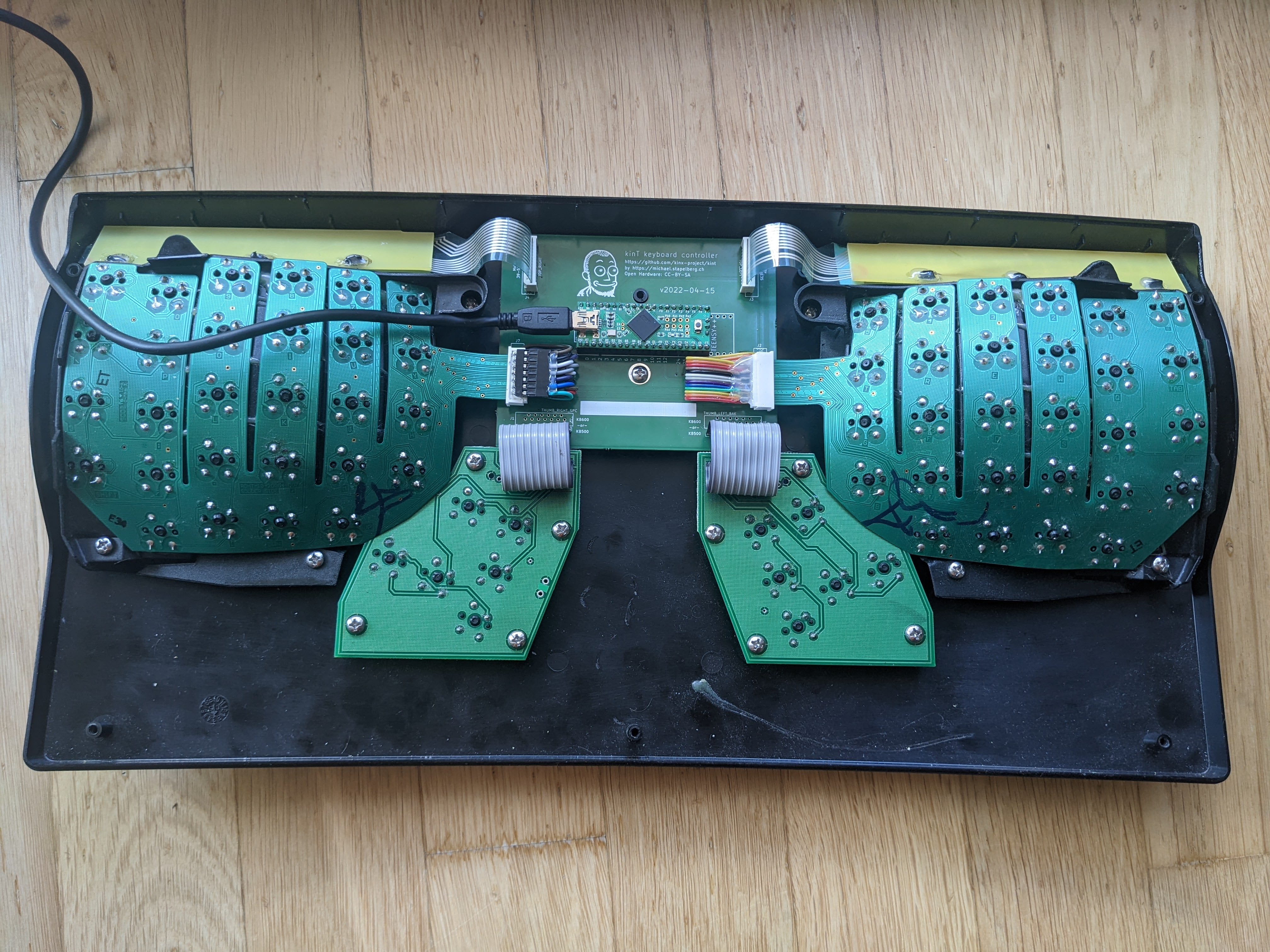
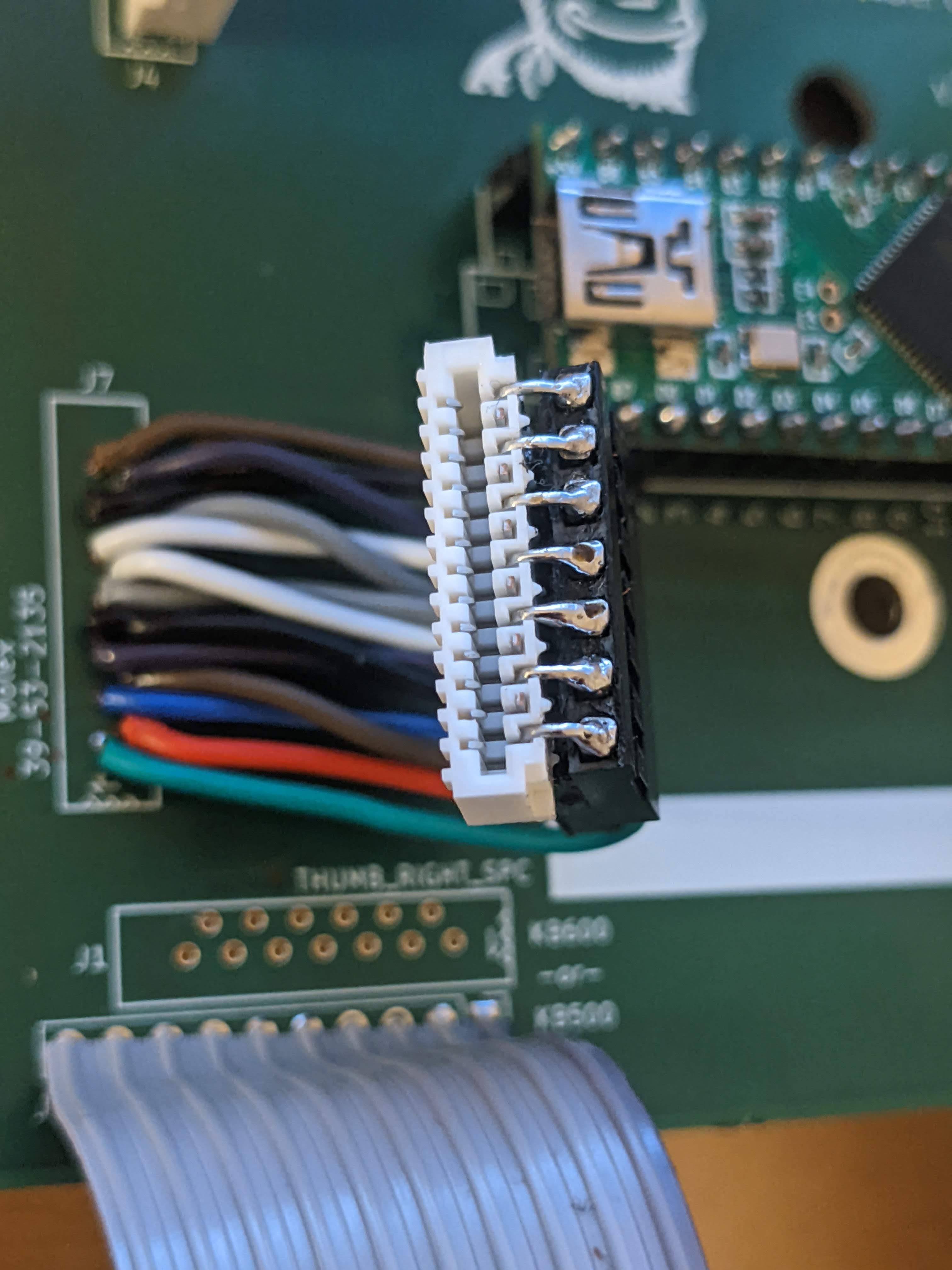
The connection can still be made by soldering wires between the Molex connector and the central board. I used Molex 39-53-2134 which has the legs at a 90 degrees angle because that’s what I got. This required fiddly bending of the legs to make the thing as slim as possible. Molex 39-53-2135 would have been much better as it can be used as is.
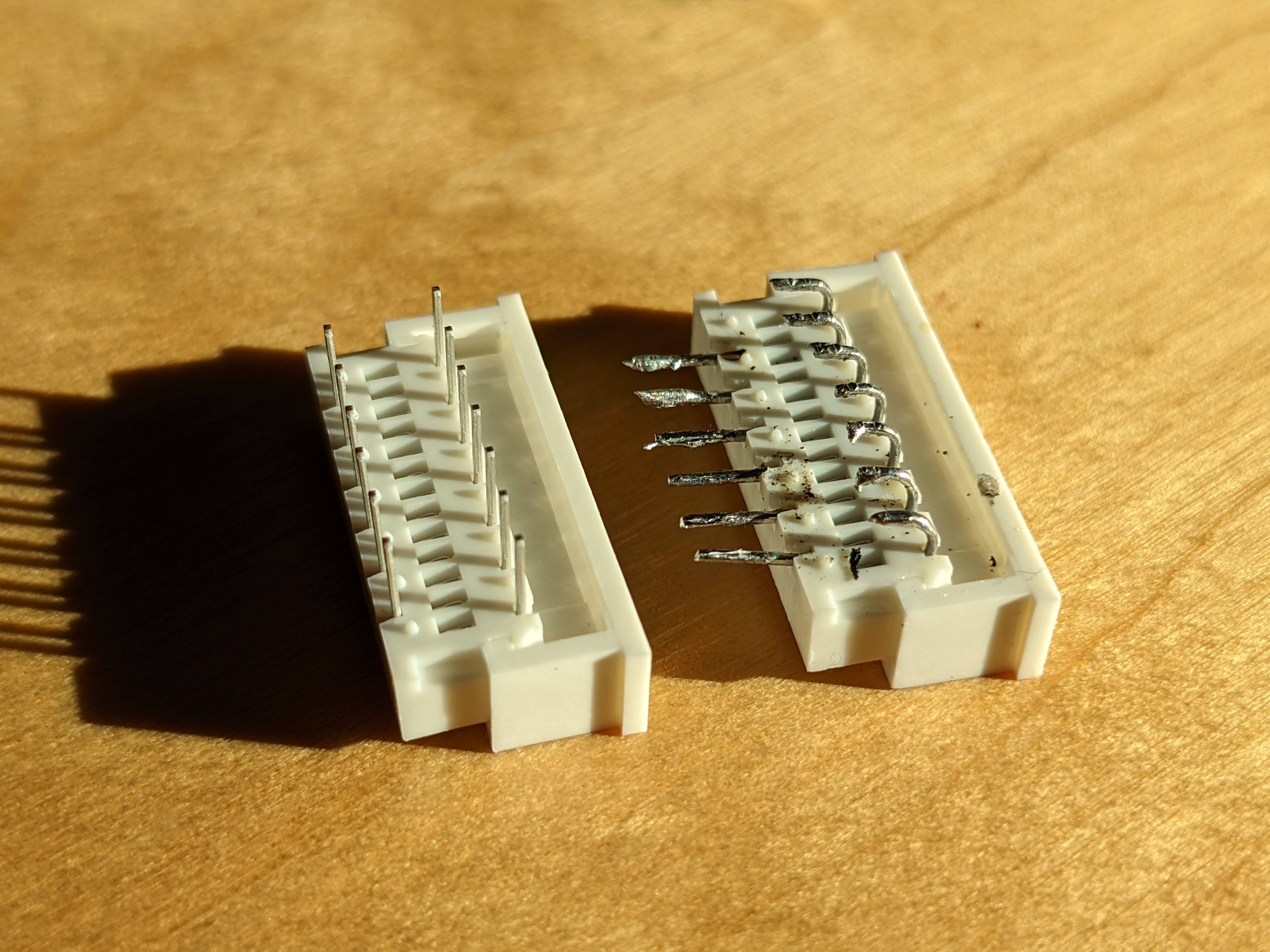
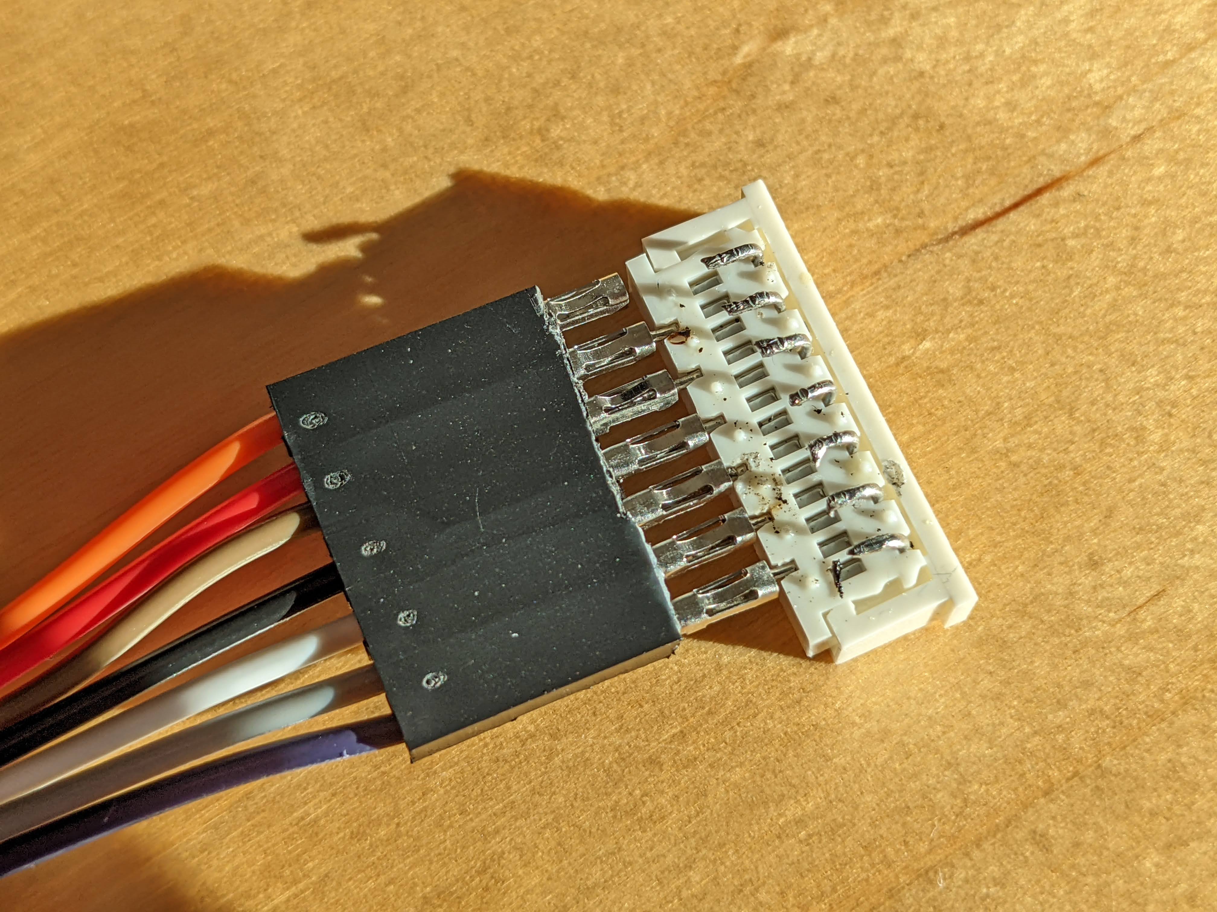
If using Molex 39-53-2134 bend its legs as in the picture
I got these 7-wire dupont cables very cheap on Aliexpress. They make the job a bit easier and keep the wires neat. Soldering the individual wires in the air is very fiddly and afterwards there is a significant risk of short-circuit.
Cut the plastic at the tip of the cable's connector with a sharp plier, for better connectivity
Pull the plastic to reveal the metal ends
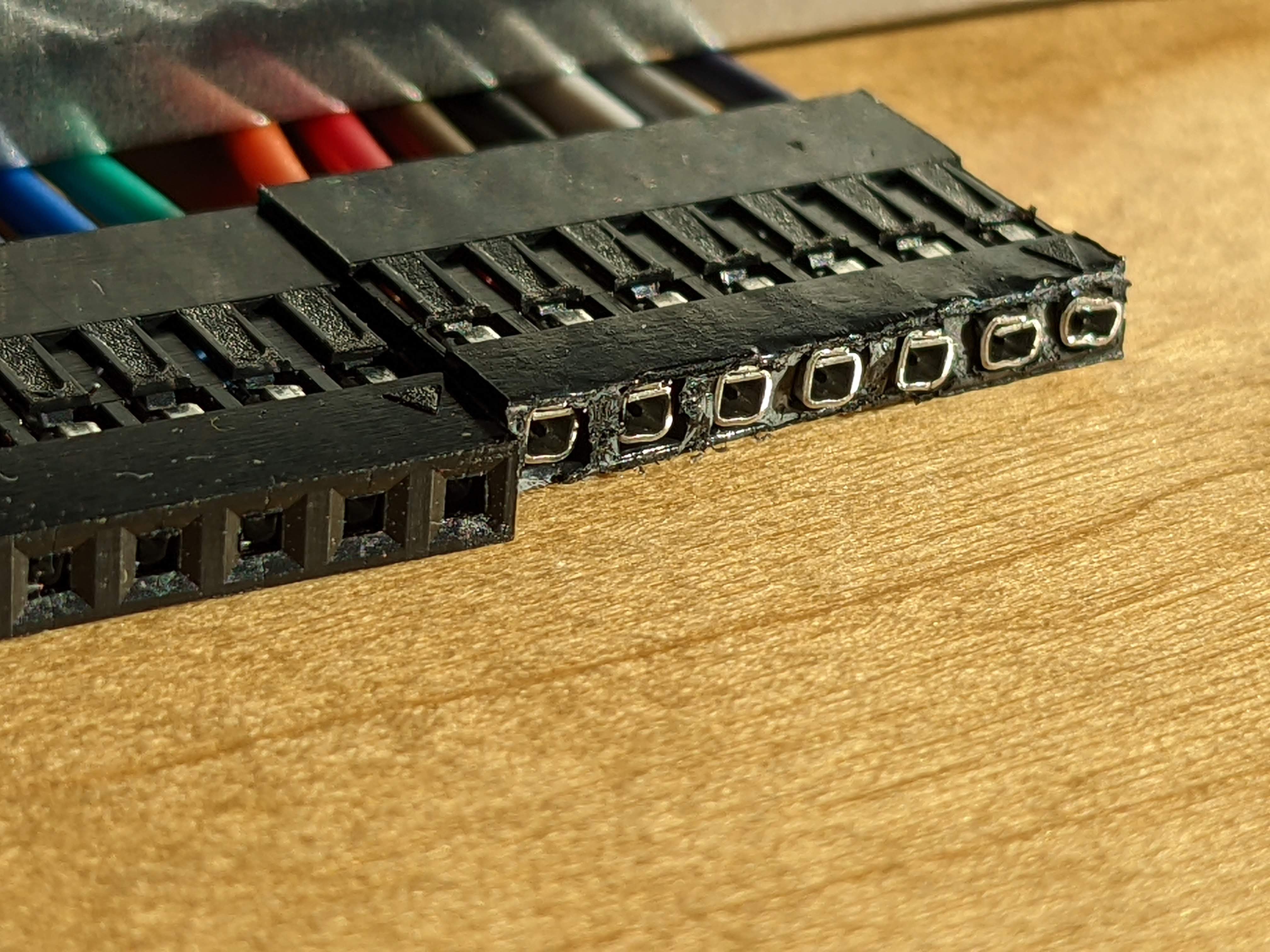
Solder one row of legs. Do it quick to prevent the black plastic melting.
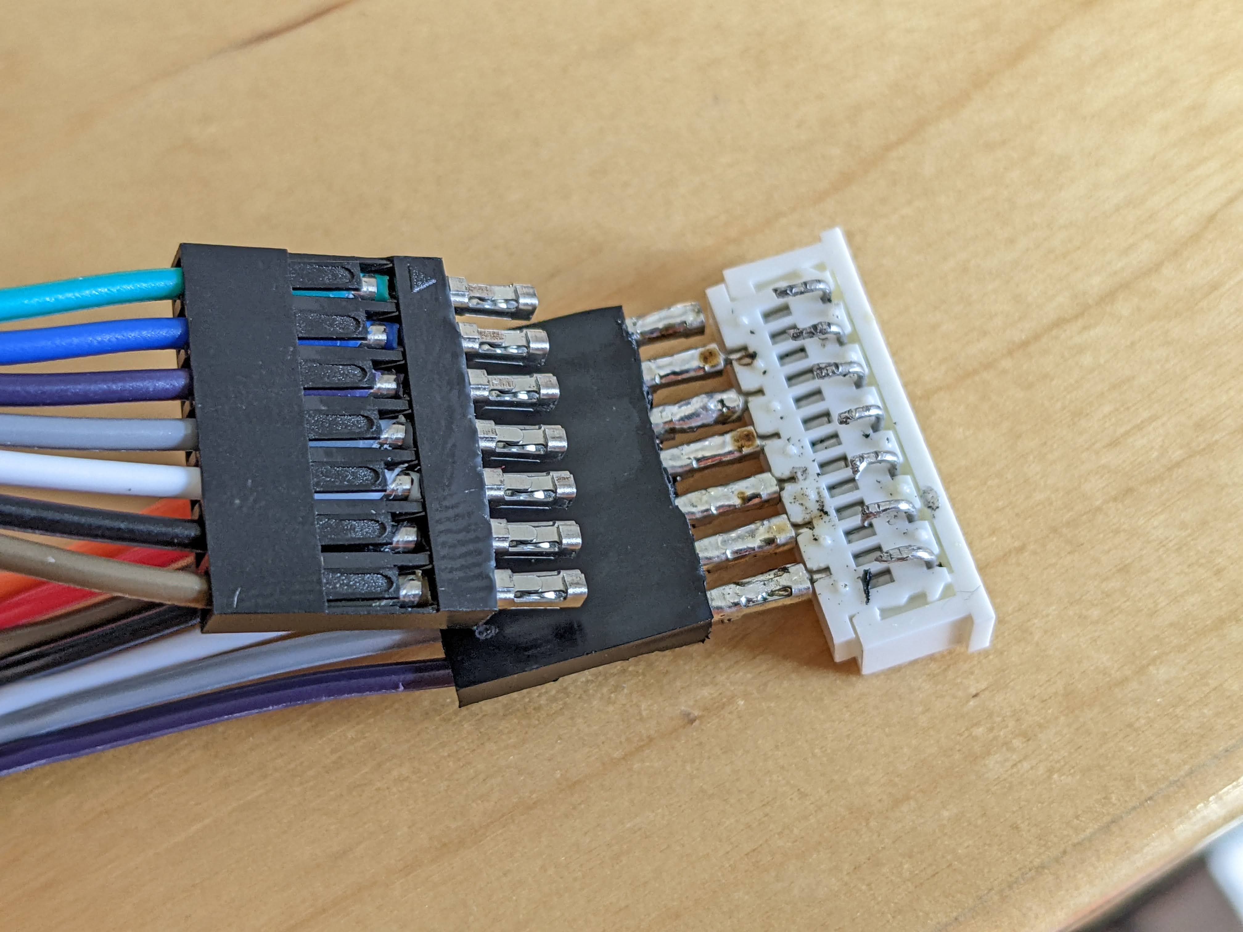
Notice the black plastic has holes on one side only. Make sure at least one of the two black connectors turns its back to the other, so to say.
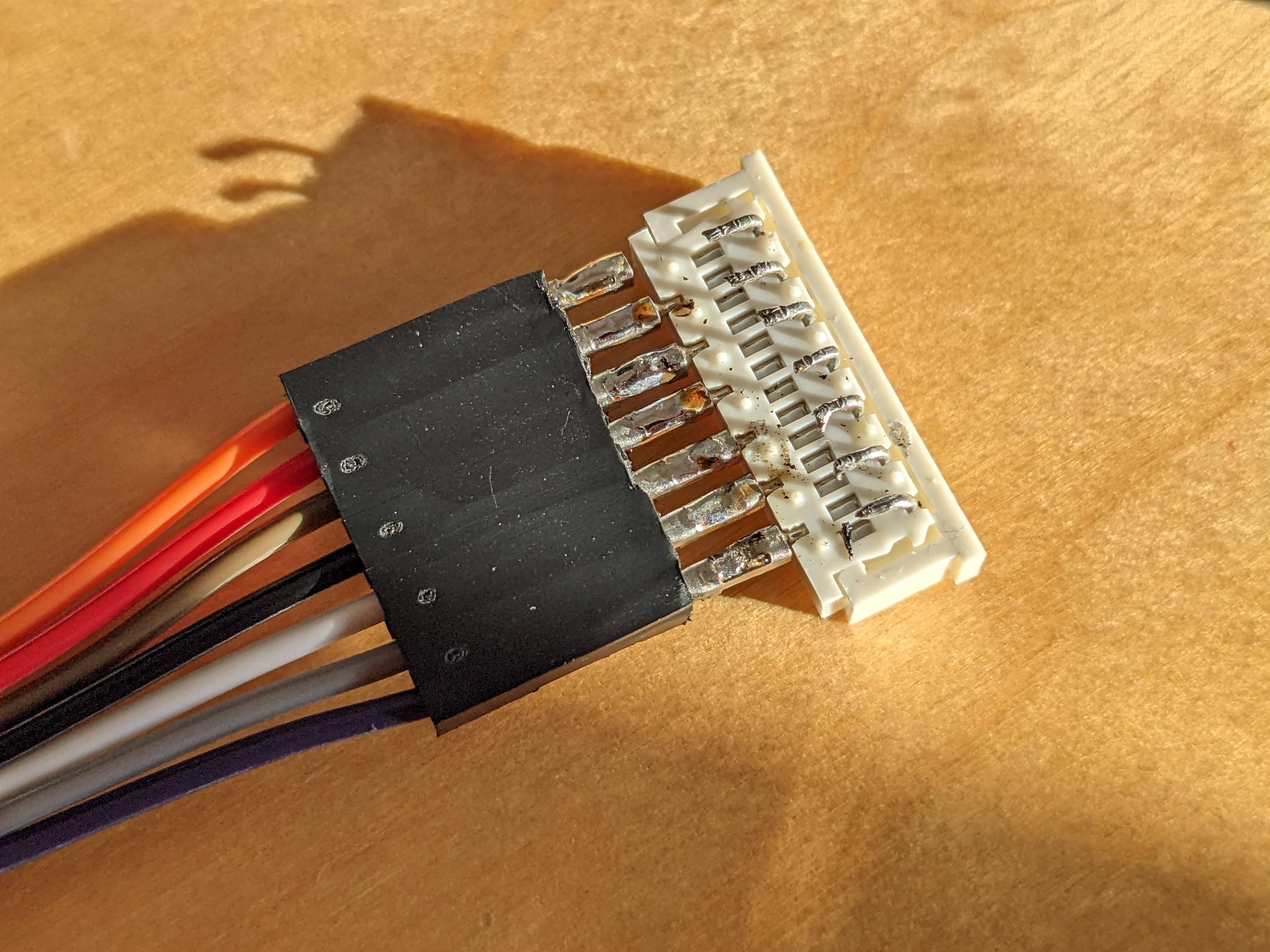
Solder the rest
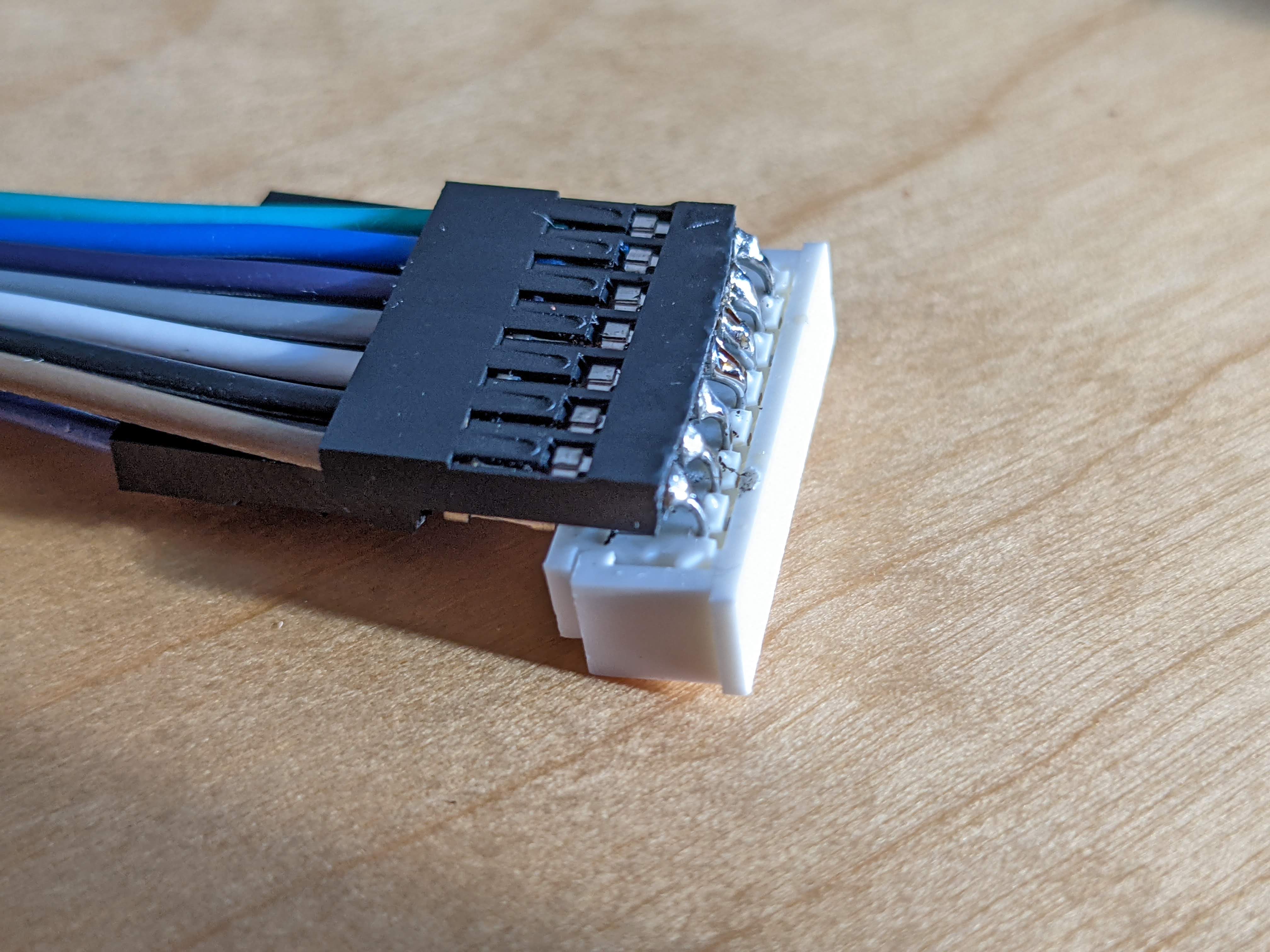
Finally pull the black plastic over the solderings
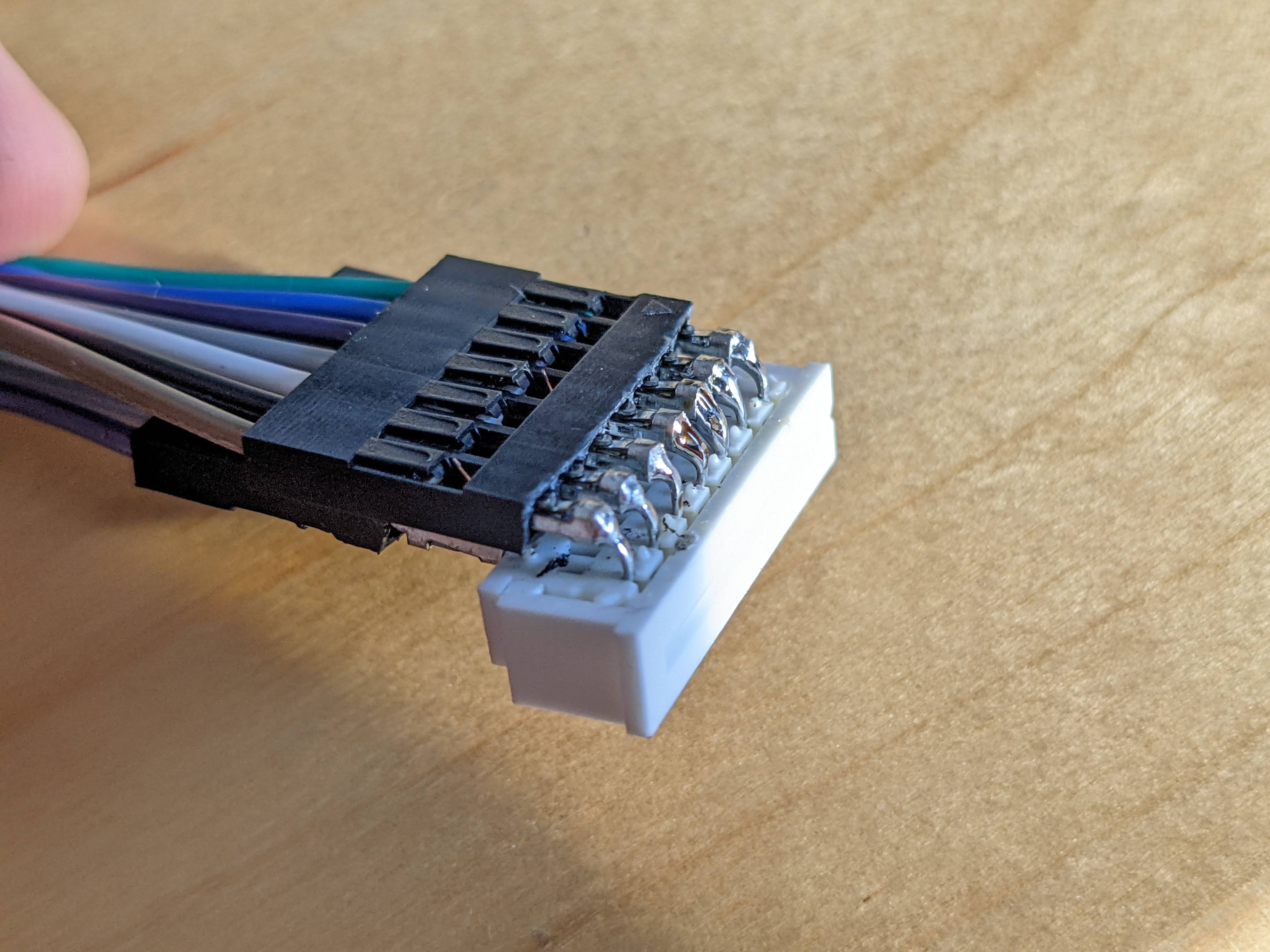
Thick wires are not an issue. The semi-rigid FPC accomodates well both thick and thin wires.
Hot glue can be used to cover the exposed metal and for extra firmness.
8 I K , Down
I was a bit disappointed to discover a column of keys does not work at all, keys: 8, I, K, , and Down.
What you can do when a key does not work is to measure the circuit conductivity.
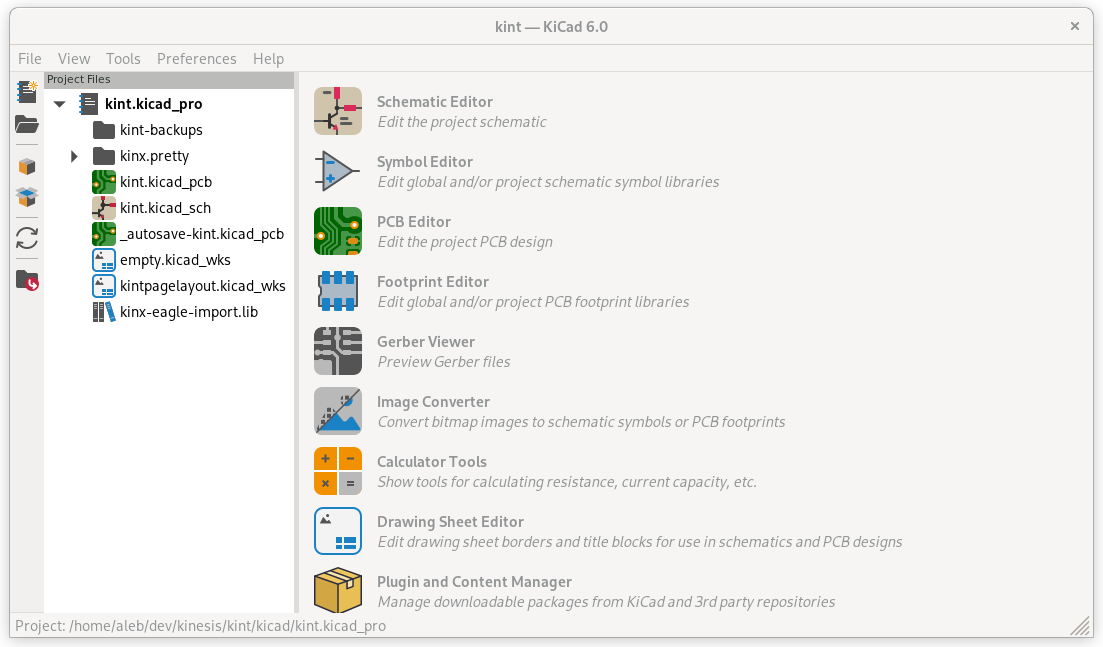
Open the Kint project in KiCad
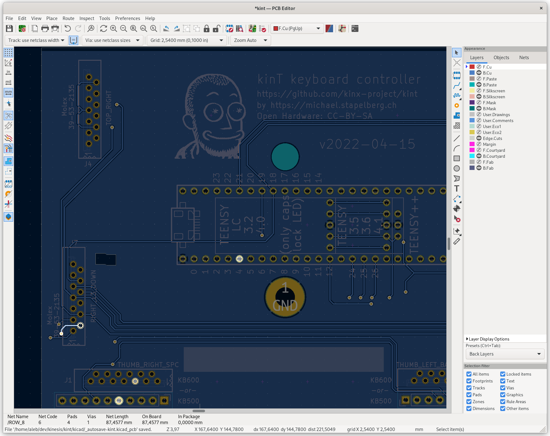
Open the PCB Editor
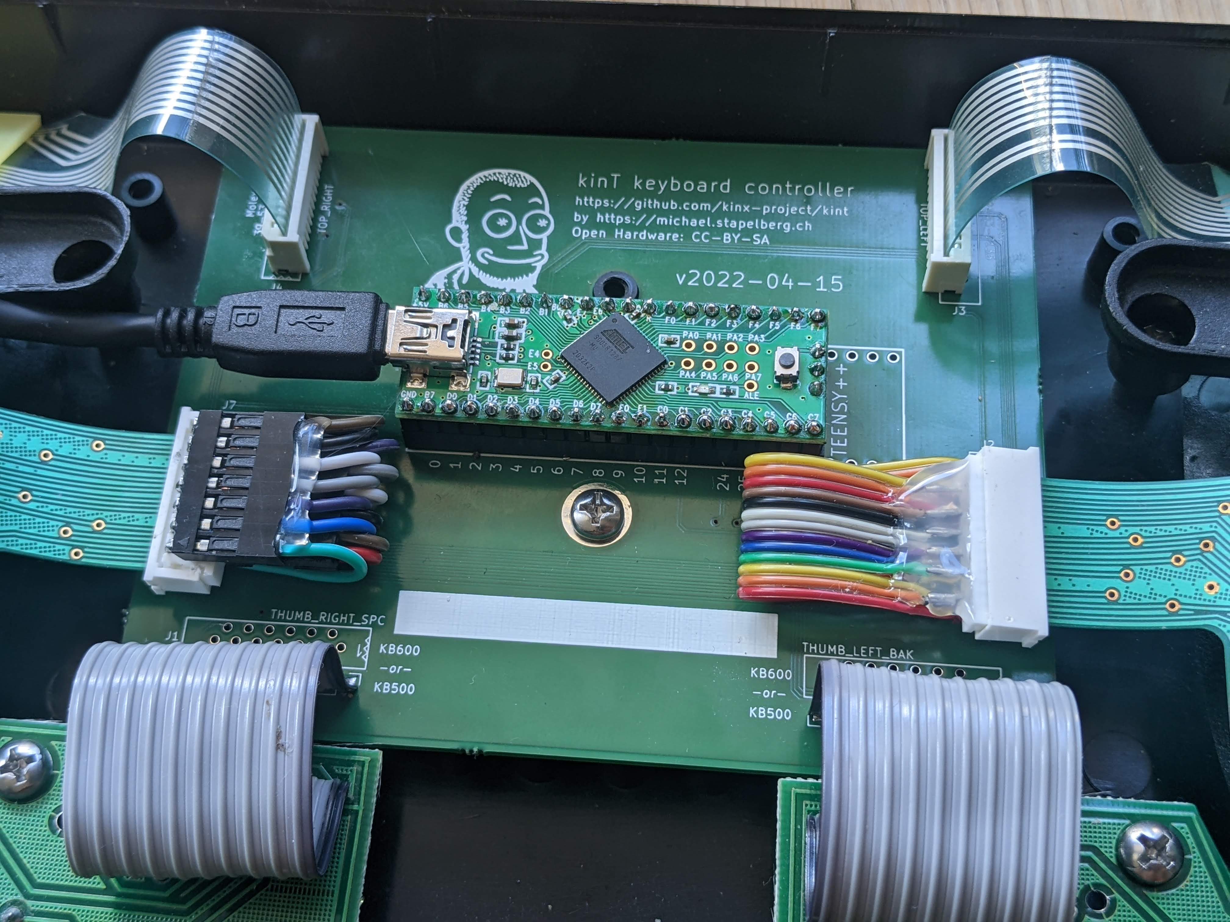
In the PCB Editor click any element and then press ` (backtick) to highlight all the paths and elements connected to it. For example in the screenshot above I clicked pin 2 of connector J7, pressed ` and the Teensy pin labeled “4” got highlighted.
I identified on the board the Molex connecting the group of keys containing the faulty keys. I took each pin of the J7 Molex connector and I made sure it’s connected to the Teensy pin as per the PCB Editor. If the PCB Editor does not show anything connected to it, skip it. Some of the Molex pins are unused despite being soldered on the board.
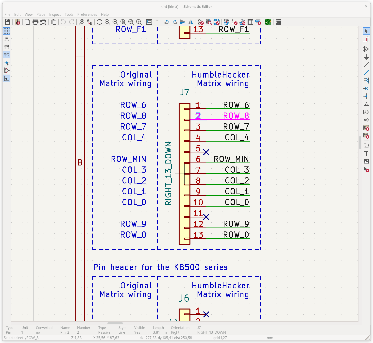
The Schematic Editor shows clearly which pins are unused
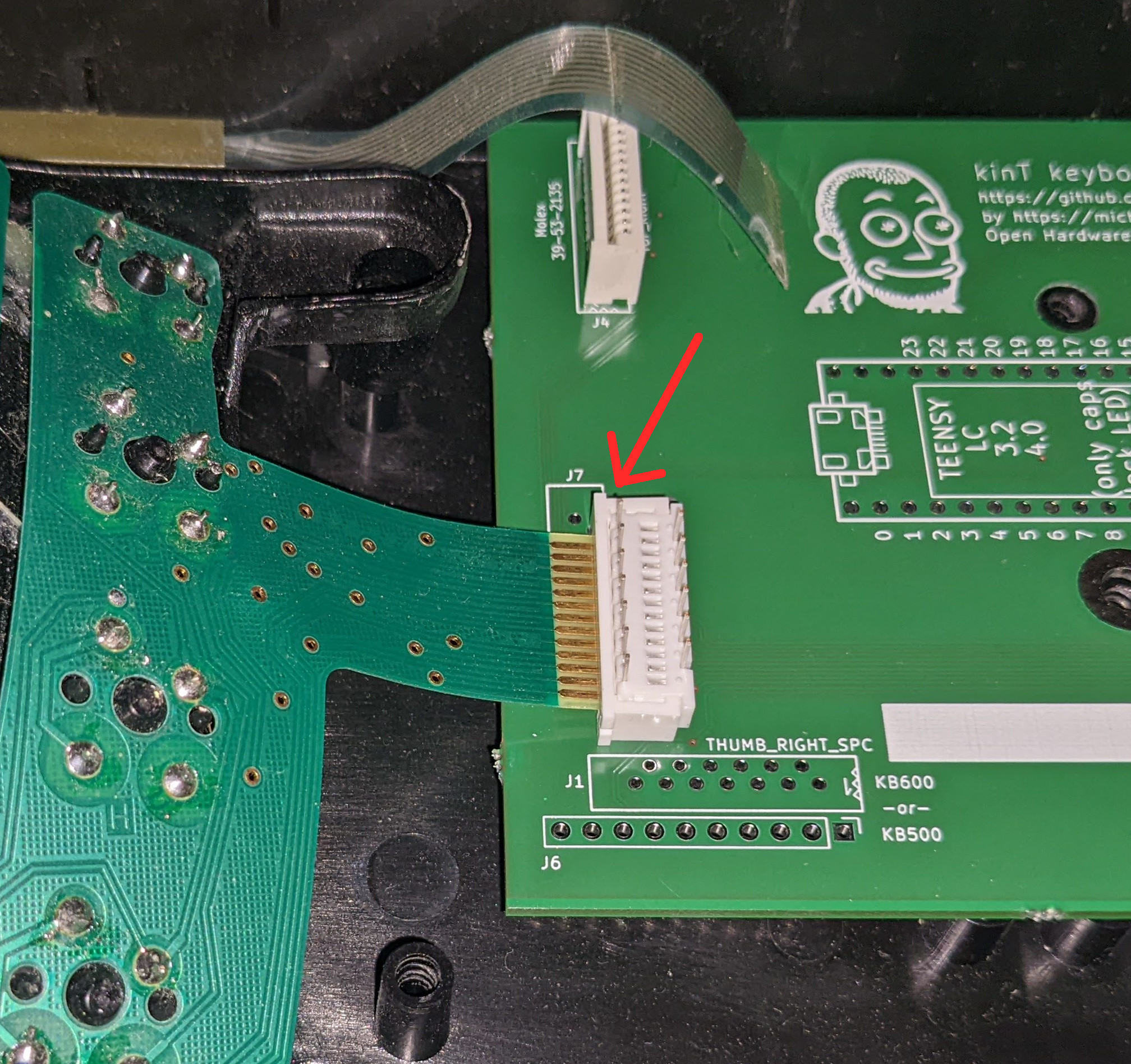
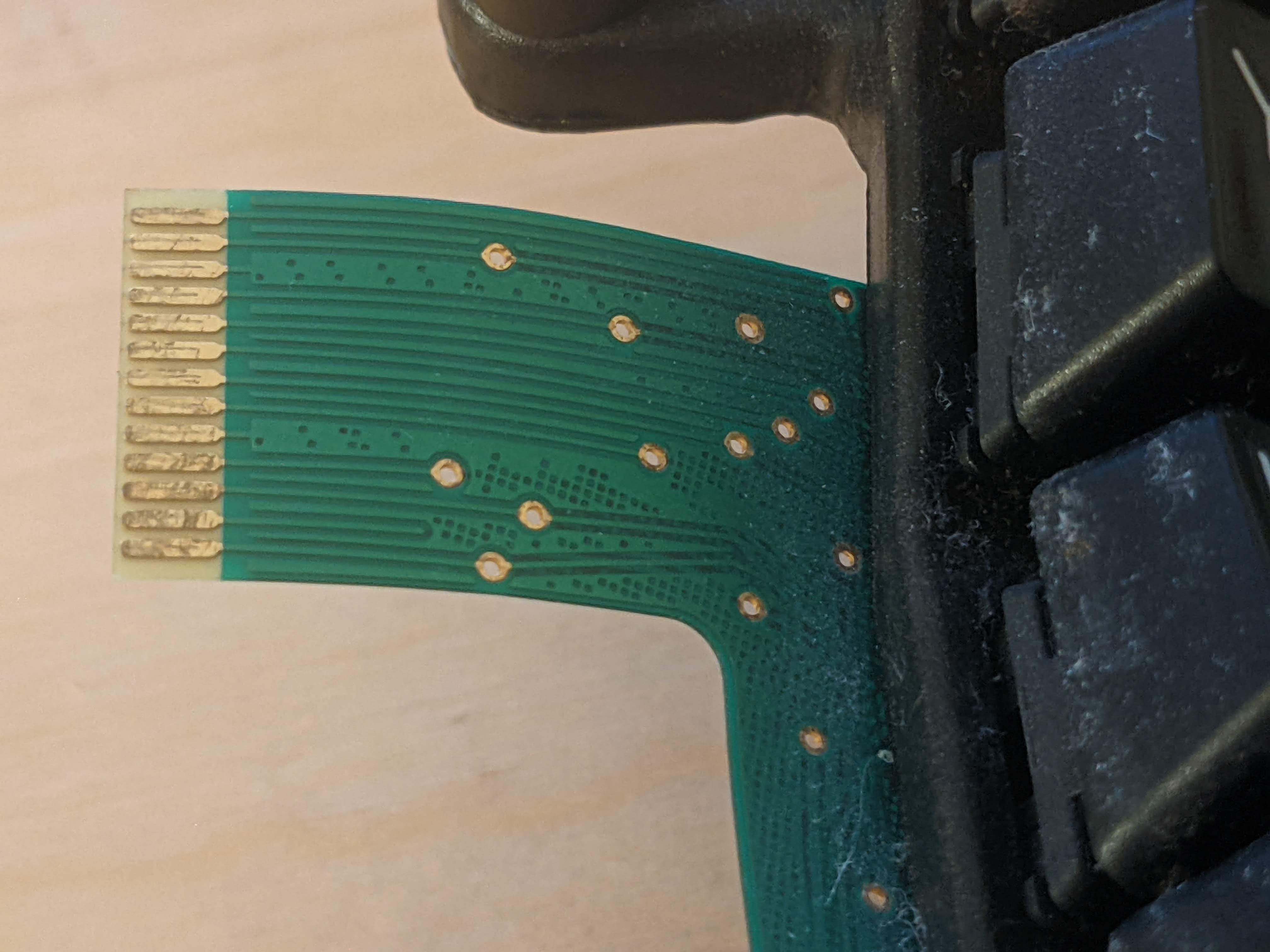
The Molex pins I inspected were all properly connected to the corresponding Teensy pins. Next I took each path on the thin FPC to make sure it’s connected to exactly one Molex pin. The first and third paths from the bottom were properly connected to the Molex pins 1 and 3, but the second was not making contact with pin 2.
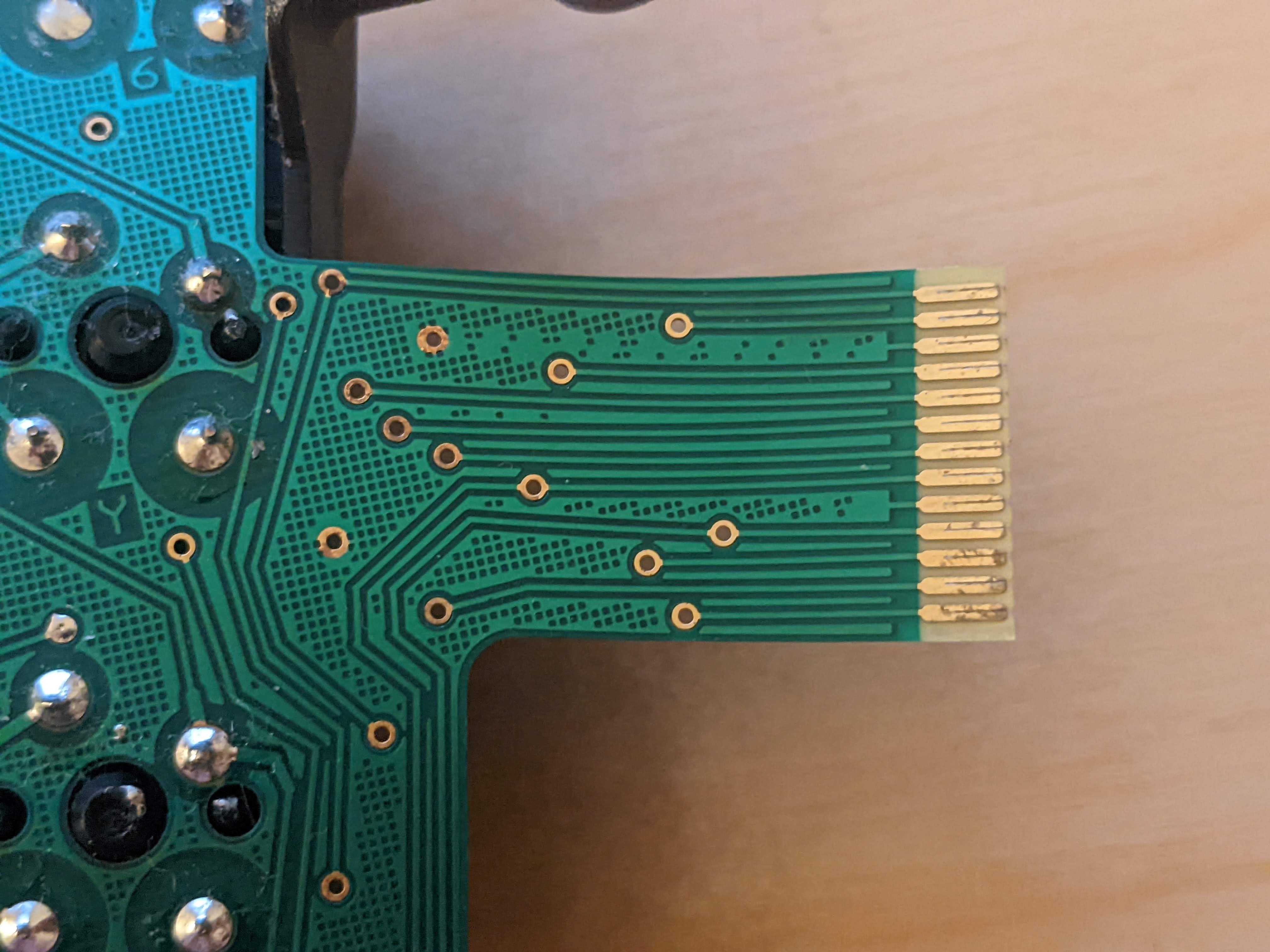
Second from the bottom was not making contact
I took apart the Molex connector expecting to see some melted plastic or displaced metal causing the issue. It looked perfect. I did notice that the Molex connector makes contact with only one side of the FPC going in, not with both sides!
Inside the Molex
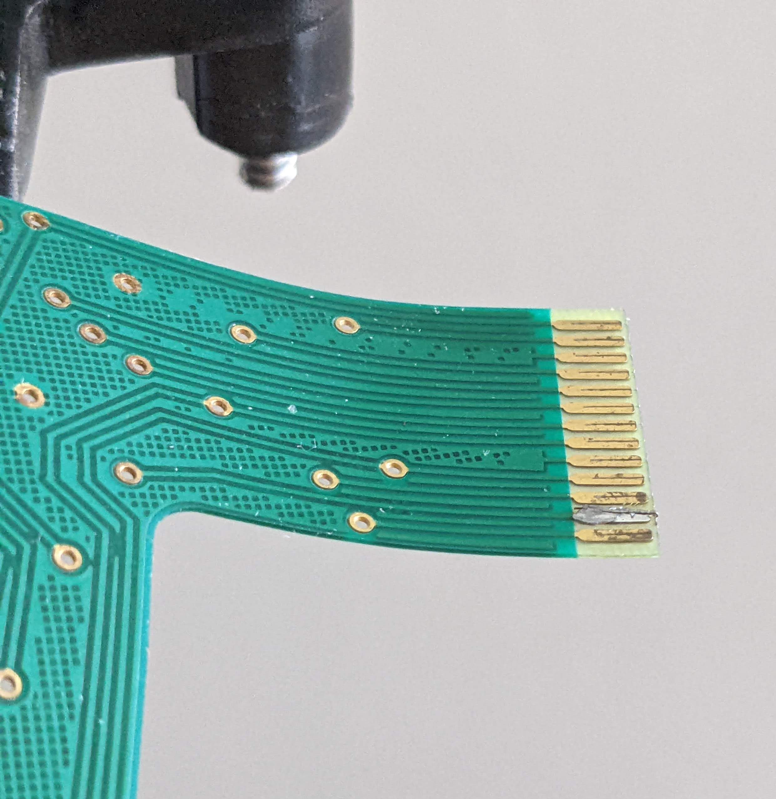
I checked the other side of the FPC and lo and behold, the second path from the bottom is just not connected.
Fixed by soldering a very thin wire to connect the two paths on the two sides of the FPC. Note if using the Molex 39-53-2135, which has straight legs, you only need to make sure the Molex connects to the proper side of the FPC!
About two months later, the connection broke for some reason. Unplugging and replugging the connector fixed it, hopefully forever.
